Click for Proffie email sign up list
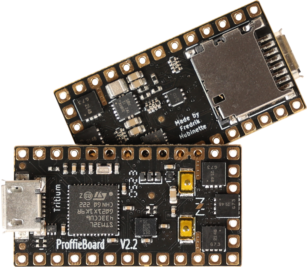
The Proffieboard is a revolution in lightsaber electronics. Fully open source this feature packed board includes smooth swing which provides the most realistic sound effects we have seen in a sound board. The v2.2 ProffieBoard utilizes the powerful STM32 microprocessor combined with a powerful motion coprocessor IMU, 3W audio amplifier, and 6 MOSFETs to control external LEDs.
Dimensions
17.8x33.2x4mm (+3.2mm with micro USB port and micro SD card)
A note on reverse polarity protection
This version of the proffieboard is the first to feature reverse polarity protection. Please note, however, that the reverse polarity protection does not really cover the LEDs. The FETs have internal bypass diodes that let power flow backward through them. For regular LEDs, this is not a problem, as power can only flow one way through a LED. Neopixels might not be so lucky though, so it may still be possible to fry your pixels by hooking up the battery backward. But the Proffieboard itself should be fine.
Wire gauges
Most pads on the proffieboard will not need to carry any significant amount of power and can use 30 AWG (very thin) wire if you choose. However, Battery- will carry the combined power of all your LEDs, which is a fair amount of power. It is recommended to use thicker wires, for these wires. There are no absolute rules for what wire gauges are required, but here is a helpful chart. (See the "chassis wiring" column.) Keeping the high-power wires short helps as well.
Programming
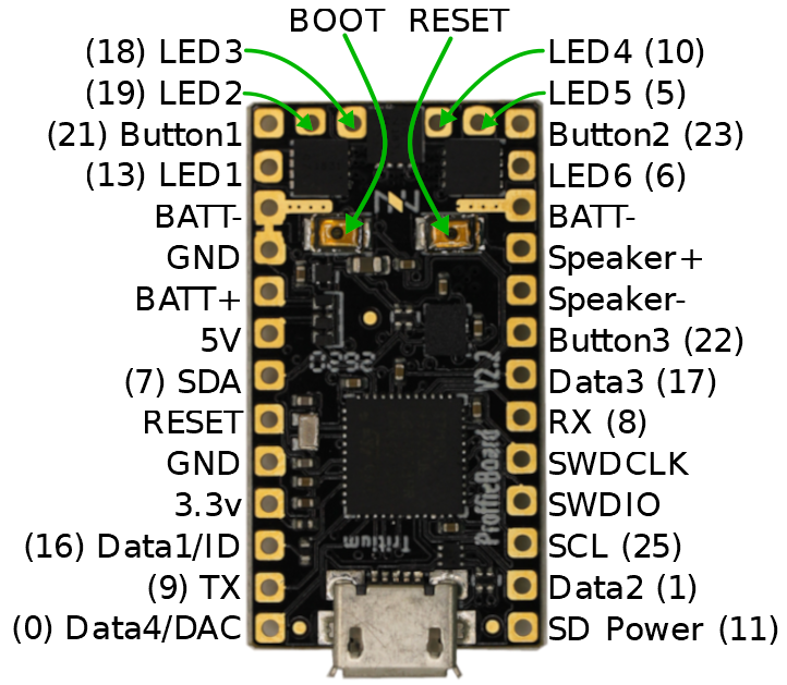
Most of the time, programming the Proffieboard is as easy as hooking up the USB cable to a computer and pressing the "upload" button in the Arduino IDE. However, an interrupted upload or a crashing program can sometimes stop that from working. If that happens, hold the boot button, then press and release the reset button. This will put the Proffieboard in bootloader mode, and press "upload" should now work.
Touch Buttons
Any of the buttons can be replaced with a touch button. To wire a touch button, simply hook up the corresponding wire to a metal surface. Note that in spite of the name, you don't actually want anybody to actually touch the touch buttons. The metal surface needs to be insulated, both from the rest of the hilt and from the fingers that will be "touching" it. In my case, I used a circuit-board clamp card in a Graflex lightsaber, then I covered it up with tape to insulate it from everything else. More details here.
Choosing Resistors
Calculating resistor values is fairly easy. Just look up how many amps the LED can handle and at what voltage it expects to achieve that current. Then the resistor value we want is (BatteryVoltage - LedVoltage) / LedAmps. And the resistor needs to handle (BatteryVoltage - LedVoltage) * LedAmps watts. Example, if the LED wants 1A @ 3.2 volts, the resistor would be (3.7 - 3.2)/1 = 0.5 ohms, (3.7 - 3.2) * 1 = 0.5 watts.
Note that I use 3.7 volts for the battery in these calculations, while Li-ion batteries tend to top out at 4.2 volts. Proffieboard can compensate for this by using PWM to reduce the total amount of power and heat generated by the LED when the voltage is higher than what it is rated for. This mode is efficient and seems to work well, but it is possible that it will reduce the life of the LEDs. If you are not comfortable with this, you should use 4.1 or 4.2 volts in the calculations above.
Multi-battery setup
The FETs on the proffieboard can handle voltages up to 30v, so it's possible to do multi-cell setups. However, "Battery+" can not handle more than ~4.5 volts. So you would need a separate battery to power the CPU. Another possibility would be to do two batteries in series, but only use one of them to power the CPU. Since the batteries would be discharged unevenly, they would have to be charged separately. In the future, I hope to make "Battery+" handle a wider range of voltages, which would make multi-cell configurations a lot simpler.
Using Data 2, Data 4, RX and TX for PWM
Data 2, Data 4, and RX and TX can be used to drive LEDs instead of neopixels or serial ports. However, a single timer is used to drive these pins. For PWM, the timer is usually set to 800Hz, however, when neopixels are used, this timer is set to 800kHz. This basically means that if you use any neopixels, all of these pins become unsuitable for driving LEDs. So, if you select a 6-segment blade + flash string in the configurator above, you cannot use the other data pins to drive neopixels unfortunately.
These ProffieBoards are made with ❤ by Tritium Electronics a US based manufacturer in Ashland, Ohio.
Documentation and Downloads
- Datasheet
- ProffieBoard Base Config File
- Software Download Page
- Troubleshooting Guide
- Please note that all troubleshooting and support will be at the following forums The Rebel Armory and the FX-Sabers online forum
- Additional FAQ for Odd Problems/LED Blade
- ProffieBoard Config Generator
- Sound Font Generator