Black Version Limited Edition (Green)
Please note that this board comes fully assembled and tested with full quality control done, please continue reading to find out how to use the board and add the components that best suit your needs. What you will need:
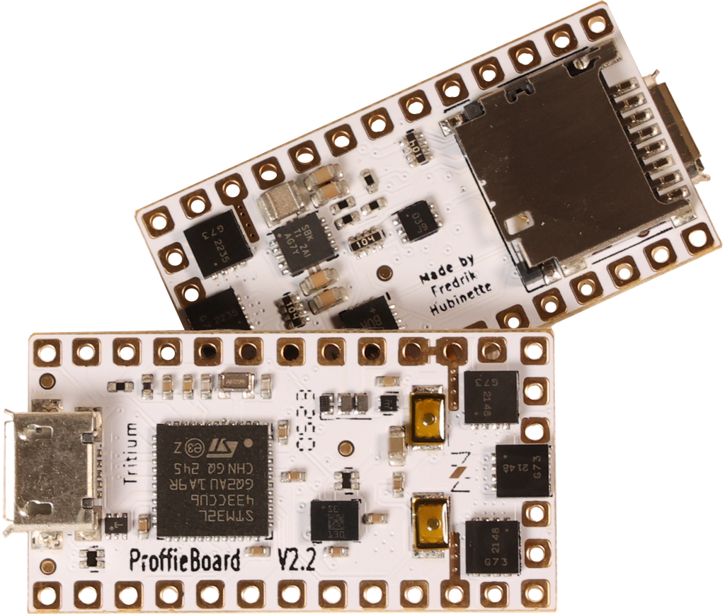
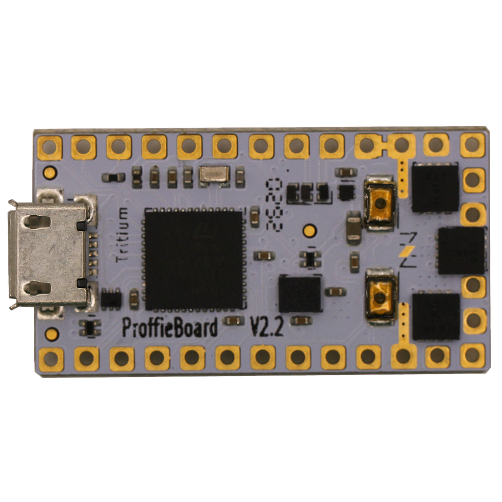
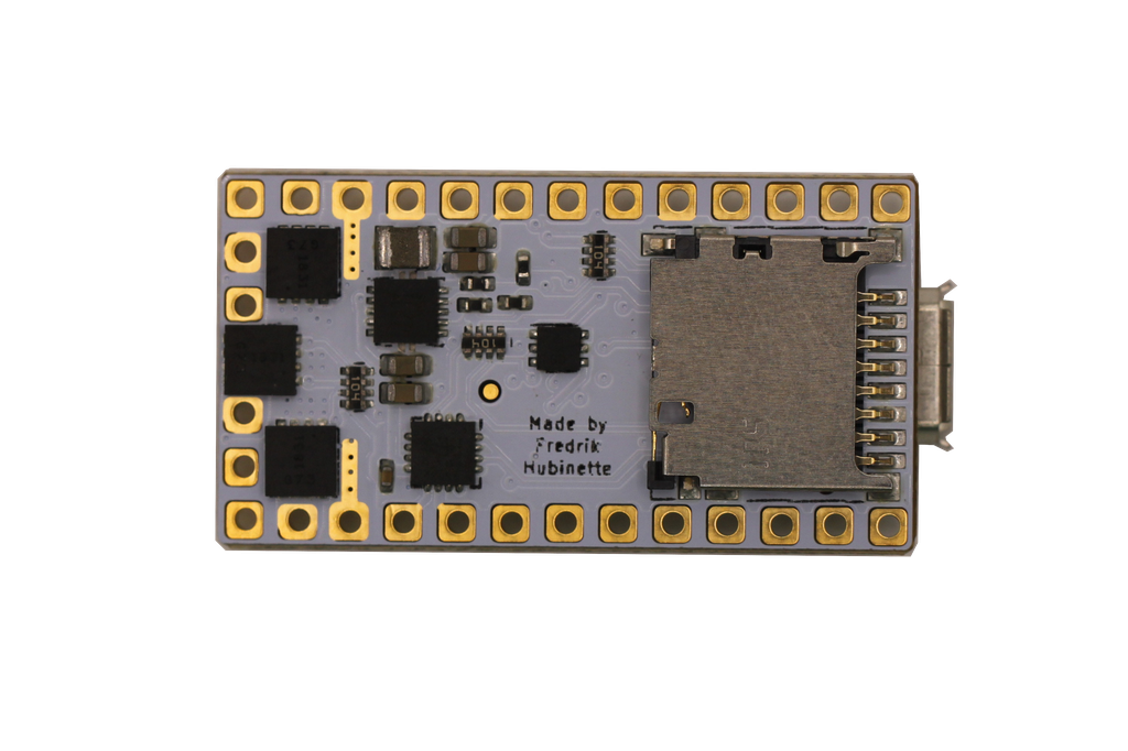
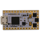
a Proffieboard V2.2 - light, sound, and motion.
Other Items (Not Included):
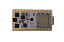
MicroSD Card (16GB)
thicker colored wire - used where power will flow to the LEDs
a 3.7v li-ion battery - most batteries will work, but make sure it can provide enough amps for whatever blade(s) you want to power.
A speaker
Software - makes the hardware actually DO stuff. (The boards come programmed, but commonly, the customer will change the config files to their liking and then reflash the board again.)
(optional) an SSD1306 display.
(optional) Bluetooth add-on
(optional) ST-Link V2 - Lets you run a debugger on the program running on the Proffieboard.
(optional) IR receiver
Please note that all troubleshooting and support will be at the following forums The Rebel Armory and the FX-Sabers online forum
BATT+ - 2.6 to 4.5-volt input, drives everything except the LEDs
BATT- - negative pad for LEDs, needs to be at the same level as GND when both are connected. Note that there are two of them, which can be useful when driving many powerful LEDs.
GND - ground for electronics except for LEDs. Note that the two GND pads are interchangeable and connected through the board.
Button 1/2/3 - Hook up to closing buttons, or potentially touch buttons.
Data 1 / ID - Normally used to measure the blade ID resistor, and if it's a neopixel blade, feed out neopixel data. For a fixed non-neopixel saber, it could be repurposed. Note that this pin has an internal 470-ohm resistor on it, so when hooked up to a neopixel blade, it does not need any resistors.
Data 2-3 - additional neopixel data outputs, or free for other purposes.
Data4/Dac - neopixel data output, free, or audio DAC output
LED 1-6 - Hooks up to the negative side of the LED (positive side of LED hooks up directly to the battery.) These pads can handle up to 30 volts.
SD Power - FET-controlled 3.3v. can be used to power down Bluetooth and display in low-power mode.
SDA, SCL - these pins are used to communicate with the gyro and accelerometer chip.
5v - generated by the proffieboard, normally it's only on when sound is playing.
3.3v - generated by the proffieboard.
SWDIO, SWDCLK - can be hooked up to an ST-LINK device and lets you debug programs running on the proffieboard.
Dimensions
17.8x33.2x4mm (+3.2mm with micro USB port and micro SD card)
A note on reverse polarity protection
This version of the proffieboard is the first to feature reverse polarity protection. Please note, however, that the reverse polarity protection does not really cover the LEDs. The FETs have internal bypass diodes that let power flow backward through them. For regular LEDs, this is not a problem, as power can only flow one way through a LED. Neopixels might not be so lucky though, so it may still be possible to fry your pixels by hooking up the battery backward. But the Proffieboard itself should be fine.
Wire gauges
Most pads on the proffieboard will not need to carry any significant amount of power and can use 30 AWG (very thin) wire if you choose. However, Battery- will carry the combined power of all your LEDs, which is a fair amount of power. It is recommended to use thicker wires, for these wires. There are no absolute rules for what wire gauges are required, but here is a helpful chart. (See the "chassis wiring" column.) Keeping the high-power wires short helps as well.
Programming
Most of the time, programming the Proffieboard is as easy as hooking up the USB cable to a computer and pressing the "upload" button in the Arduino IDE. However, an interrupted upload or a crashing program can sometimes stop that from working. If that happens, hold the boot button, then press and release the reset button. This will put the Proffieboard in bootloader mode, and press "upload" should now work.
Touch Buttons
Any of the buttons can be replaced with a touch button. To wire a touch button, simply hook up the corresponding wire to a metal surface. Note that in spite of the name, you don't actually want anybody to actually touch the touch buttons. The metal surface needs to be insulated, both from the rest of the hilt and from the fingers that will be "touching" it. In my case, I used a circuit-board clamp card in a Graflex lightsaber, then I covered it up with tape to insulate it from everything else. More details here.
Choosing Resistors
Calculating resistor values is fairly easy. Just look up how many amps the LED can handle and at what voltage it expects to achieve that current. Then the resistor value we want is (BatteryVoltage - LedVoltage) / LedAmps. And the resistor needs to handle (BatteryVoltage - LedVoltage) * LedAmps watts. Example, if the LED wants 1A @ 3.2 volts, the resistor would be (3.7 - 3.2)/1 = 0.5 ohms, (3.7 - 3.2) * 1 = 0.5 watts.
Note that I use 3.7 volts for the battery in these calculations, while Li-ion batteries tend to top out at 4.2 volts. Proffieboard can compensate for this by using PWM to reduce the total amount of power and heat generated by the LED when the voltage is higher than what it is rated for. This mode is efficient and seems to work well, but it is possible that it will reduce the life of the LEDs. If you are not comfortable with this, you should use 4.1 or 4.2 volts in the calculations above.
Multi-battery setup
The FETs on the proffieboard can handle voltages up to 30v, so it's possible to do multi-cell setups. However, "Battery+" can not handle more than ~4.5 volts. So you would need a separate battery to power the CPU. Another possibility would be to do two batteries in series, but only use one of them to power the CPU. Since the batteries would be discharged unevenly, they would have to be charged separately. In the future, I hope to make "Battery+" handle a wider range of voltages, which would make multi-cell configurations a lot simpler.
Using Data 2, Data 4, RX and TX for PWM
Data 2, Data 4, and RX and TX can be used to drive LEDs instead of neopixels or serial ports. However, a single timer is used to drive these pins. For PWM, the timer is usually set to 800Hz, however, when neopixels are used, this timer is set to 800kHz. This basically means that if you use any neopixels, all of these pins become unsuitable for driving LEDs. So, if you select a 6-segment blade + flash string in the configurator above, you cannot use the other data pins to drive neopixels unfortunately.

Documentation and Downloads
- Please note that all troubleshooting and support will be at the following forums The Rebel Armory and the FX-Sabers online forum
- Additional FAQ for Odd Problems/LED Blade