Garage Door Opener
A quick and easy project for all ages
So recently I have been looking for a solution to open my garage door with having the remote that was provided with the opener. This is a great idea for people like myself who tend to lock keys in the house. I wanted to have a keypad that I had the pin for that would open the garage door or be repurposed for many things.
So the first step was to see what one of my previous co-workers had come up with 5 or more years ago when we renovated our headquarters. We have a similar set up for our shipping terminal so that our FedEx and UPS guys could have a code that unlocked a door that had the packages for the day that needed to be shipped out. I will provide a link to that project because it is very in depth and covers everything.
Here
So now that I had an idea and a direction to look in. I started the project. I went to our website and tried to see if we had a product that could already do everything that I was looking for. So after looking for a little bit. I was able to find an all in one module that does everything that I wanted it to do. The only problem was the price. My goal was to do this project for under $25! The module that I found was just shy of $50 coming in at $47.89 which was almost double my budget
Now my task was to find the cheapest microcontroller to be the brains of my project. Recently we put our Arduino Uno R3’s on sale for only $9.95 a unit so I had my brain picked out. Next was the keypad. Again going with the cheapest keypad that we have. It just happens to be a 12 button keypad that comes in at a
So here is a parts list of what is needed for this project.
Here are the tools that I used as well
-
Soldering Iron (This is the iron that I have been using for the past 5 years with nothing failing)
-
Solder (It’s always nice to stray away from any form of lead)
-
Soldering Mat (To protect your table from burns and marks)
-
Jumper Wires (These are always nice to have and it makes mocking up really easy)
Now that we have a parts list and all the tools that are needed ready. We can start by putting the
Beefcake Relay Control
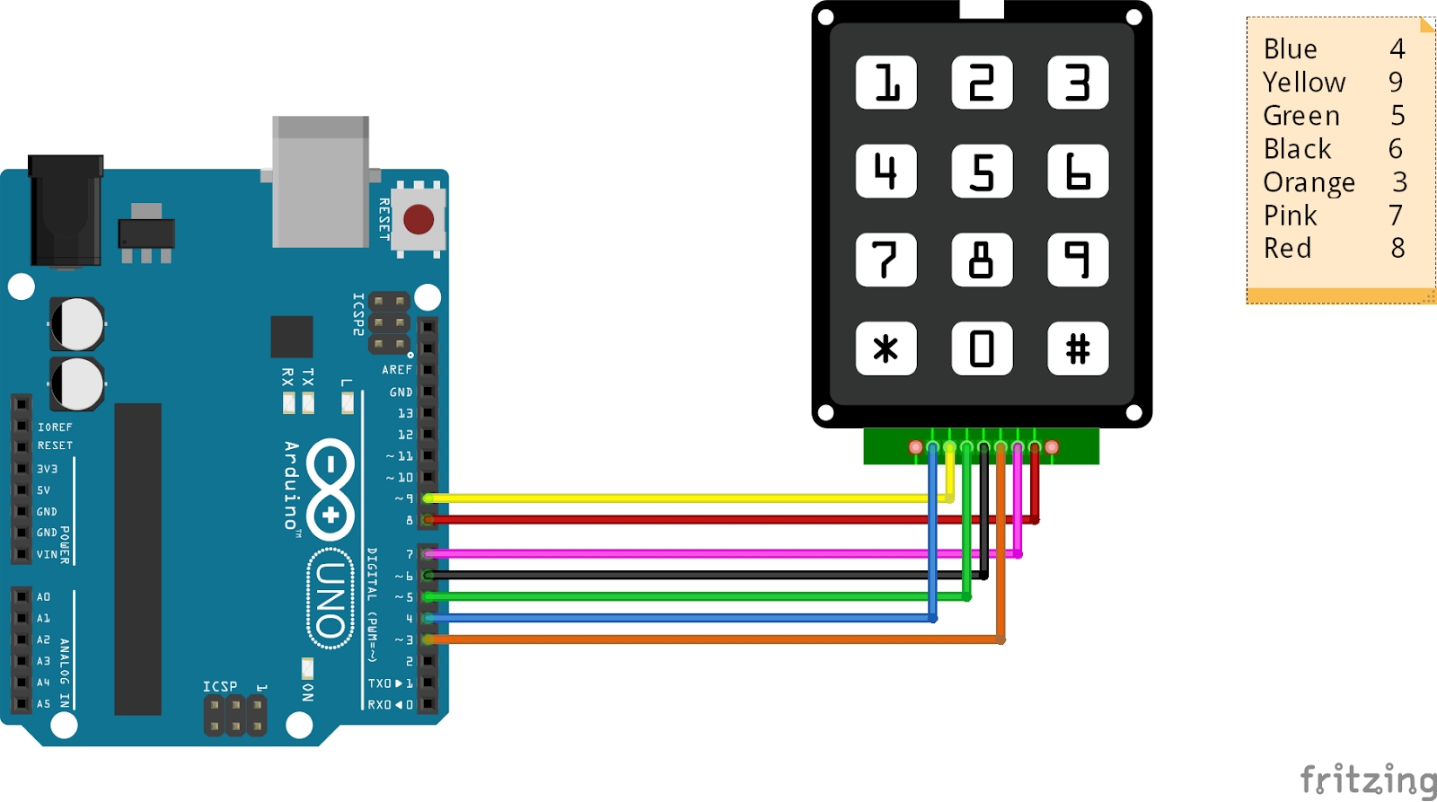
Okay, now that all the modules that need put together are done, we can start with the construction of the “Garage Door Opener” This is just proof of concept so I will not be showing the full assembly with the full-length wires ran but just short lengths of wire so that you can see how the module works. You can customize the actual length of the wires to meet your needs. I soldered the jumper wires to the keypad to make testing easy as seen in the picture below and I also included a picture diagram to make it easier to follow as well.


This is where some fun things come into play. Since there are so many different variants of keypads, you have to use the schematic of the keypad that you are using to determine the pinout of the board. If you are using the one that I linked above. I have done all the fun work for you. Here is a table that shows which pin on the keypad corresponds with which pin on the Arduino.
|
Keypad |
Arduino |
|
1 |
na |
|
2 |
4 |
|
3 |
9 |
|
4 |
5 |
|
5 |
6 |
|
6 |
3 |
|
7 |
7 |
|
8 |
8 |
|
9 |
na |
Hopefully, the above table is able to help you with this hookup procedure for connecting the keypad to the Arduino. Below I will attach a picture diagram that I created to go along with this project.
Once you have your keypad hooked up to your Arduino you can start with some code to test the keypad and make sure that everything is working how it should be. What you will need to do is open the Arduino IDE so that you can upload your code to the Arduino. If you don’t have the Arduino IDE you can click this link
Here
#include <Keypad.h> //Here is a link to the library
const byte ROWS = 4;
const byte COLS = 3;
char keys[ROWS][COLS] = {
{'1', '2', '3'},
{'4', '5', '6'},
{'7', '8', '9'},
{'*', '0', '#'}
};
byte rowPins[ROWS] = {9, 8, 7, 6};
byte colPins[COLS] = {5, 4, 3};
Keypad customKeypad = Keypad(makeKeymap(keys), rowPins, colPins, ROWS, COLS);
void setup(){
Serial.begin(9600);
}
void loop(){
char customKey = customKeypad.getKey();
if (customKey){
Serial.println(customKey);
}
}
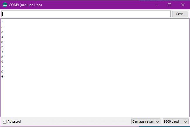
With this above code, you will be able to test the keypad through the serial monitor that is built into the Arduino IDE. This is a very basic code that can be changed to your exact keypad very easily. Once this code is uploaded to your device and you run the serial monitor, when you press a key on the keypad, it should appear in the serial monitor log. Make sure to press all the keys to make sure that all the numbers and symbols appear correctly.
This is what you should see in the serial monitor log if the keypad and code
Now that we know that the keypad functions properly we can move on to the next step in this project. The next thing that we need to do is add the relay board to this setup. I will attach a diagram below showing how it should all be connected.

The relay board that I picked needs 3 connections to operate correctly. One to 5-volt power, one to the ground, and the final to the pin that you choose to activate the relay. In my case, I chose 13 because of the onboard LED on the Arduino using the same pin so it allows for easy testing. Now you get to see the final code that will be uploaded onto the module.
#include <Keypad.h> //Here is a link to the library http://playground.arduino.cc/code/Keypad
char* secretCode ="9876#"; //First Secret Pin
char* secretCode1 ="1234#"; //Second Secret Pin
int position = 0;
const byte ROWS = 4; //Set this to the number of rows on the
const byte COLS = 3; //Set this to the number of columns on the
char keys[ROWS][COLS] = {
{'1', '2', '3'}, //Defines the layout of the pinpad that is being used
{'4', '5', '6'}, //Edit this to the layout of your pinpad
{'7', '8', '9'},
{'*', '0', '#'}
};
byte rowPins[ROWS] = {9, 8, 7, 6}; //Defines which pins on the arduino go with what button on the pinpad
byte colPins[COLS] = {5, 4, 3}; //Use the pinpads schematic to find this out
Keypad keypad = Keypad(makeKeymap(keys), rowPins, colPins, ROWS, COLS);
int greenPin = 13; //Sets Pin 13 as the trigger for the relay
int redPin = 12; //Used as a debug to make sure that the module is ready for use
void setup()
{
pinMode(redPin, OUTPUT); //This sets the pins as outputs on the arduino
pinMode(greenPin, OUTPUT);
setLocked(true);
}
void loop()
{
char key = keypad.getKey(); //This sets the board as locked until the secret code is typed in
if (key == '*'|| key == '5'|| key == '8'|| key =='9'|| key =='0' ) { //This allows you to use a character to restart the code and is needed to be pressed before the secret code is typed in. This also prevents random guesses of the password.
position = 0;
setLocked(true);
}
if (key == secretCode[position]) { //This allows the secret code to be used to unlock the board
position++;
}
if (key == secretCode1[position]){ //This allows the secret code to be used to unlock the board
position++;
}
if (position == 6) {
setLocked(false);
}
delay(50);
}
void setLocked(int locked)
{
if (locked) {
digitalWrite(redPin, HIGH);
digitalWrite(greenPin, LOW);
}
else {
digitalWrite(redPin, LOW);
digitalWrite(greenPin, HIGH);
delay(1000);
digitalWrite(redPin, HIGH);
digitalWrite(greenPin, LOW);
}
}
Once you have uploaded the code and tweaked it to your application and your liking. This project is finished. I have tried to make sure to leave comments in the code for what everything does.
If you wish, you can also follow along to the video that I have put together for this project too. I will also include a link to a kit that has everything that you need to buy for this project in one click. I hope this will be able to help without you worrying about not receiving the correct units. If you guys have any more ideas for projects to do, please let me know by sending an email to [email protected] and I will see what solutions I can come up with and hopefully we will be able to do monthly projects if not weekly depending on the complexity of the module.